XPS (Crystal Plate Scanner)
- 1. Introduction
- 2. XPS Menu
- 3. XPS Translations
- 4. XPS Plate ID
- 5. XPS Status
- 6. Crystallization Plate
- 7. Data Collection
- 8. Crystal page
- 9. TV window
1. Introduction
The "XPS"-page can be accessed by selecting the corresponding tab in the main window. The page is available only if the configuration file carries the line XPS USE (see chapter Configuration File in section Input). Here, you can access all functions of the optional sample changer.
The "XPS"-page features several work areas:
- a popup window for entering physical crystallization plate parameters (see 1.2)
- an entry "XPS" in the menu of the main page(see 2.)
- an area for driving x,y-translations(see 3.)
- an area for providing an optional plate ID(see 4.)
- an area containing the status information of a selected drop(see 5.)
- an area containing a visual representation of the crystallization plate(see 6.)
Furthermore, special features exist in other windows:
- CRYSTAL page: control about x,y tranlation motors (see 8.).
- TV window: point and click operation for x,y (see 9.).
1.1 Principles of Operation
The crystal plate scanner (XPS) is an extension of the desktop beamline. The extension allows for mounting a standard crystallization plate, e.g. the Greiner CrystalQuick-X plates with dimensions of 85.5 x 127.8 mm and 2 drops per well. The XPS system features an orthogonal arrangement of x,y-translations for the entire plate. The motors are called XPS_X and XPS_Y from here on. To mount the XPS system, some optional components of the mardtb have to be dismounted, in particular the beamstop, the bracket holding the cooling head of a cryo-device and the tube for the cryogenic exhaust. Due to space limitations it is also desirable to dismount the entire PHI-axis. With a mounted PHI-axis, only 2/3 of the drop positions of the crystallization plate can be accessed. For mardtb instruments with a built-in motorized goniometer head, less than 1/2 of the crystallization plate is accessible. To access the remaining ones, the plate has to be rotated manually by 180. degrees. Since technical details are not subject of this manual, here we concentrate on the software interface and assume that the crystal plate scanner has been taken in operation with all the technical requirements. For simplicity, we assume that the PHI-axis is not present and that all positions of the crystallization plate can be accessed by driving the motors without running into collisions.
Due to the way the motors for x- and y-translation are mounted with respect to the camera (and X-ray beam), the origin x,y=[0.0,0.0] is in the UPPER RIGHT corner when seen along the beam, not in the upper left corner! Therefore, a positive x-translation is from right to left, i.e. the XPS_X values increase when moving from left to right. The y-translation is as expected, i.e. XPY_Y values increase as the the plate moves up.
The crystallization plate will fit into the XPS system in 2 distinct orientations named TOP and BOTTOM with the viewing direction along the beam:
- TOP: drop A-1-a is in the upper right hand corner
- BOTTOM: drop A-1-a is in the lower left hand corner
Each drop on the plate can exist in 5 distinct states that are color coded:
- UNKNOWN: x,y-coordinates are unknown (white)
- PREDICTED: x,y-coordinates are predicted based on given parameters (grey)
- CONFIRMED: x,y-coordinates have been explicitely confirmed (dark red)
- QUEUED: drop has been selected for a data collection queue (orange)
- DONE: after collecting data on the drop, its status automatically changes to DONE (green)
1.2 Crystallization Plate Setup
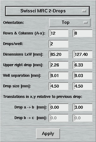
The "Crystallization Plate Setup" is a popup window that pops up when the menu item "Setup" is chosen from the XPS menu in the menu bar of the main page or when the "Setup" button is pressed in the top left corner of the graphical representation of the crystallization plate area.
For correctly handling the crystallization plates, it is mandatory to define the physical properties of the given type of plate. It is likely, that only very few types of crystallization plates are being used in a lab, so the procedure of having to find suitable parameters needs to be done only very few times. Furthermore, a couple of predefined parameter sets are already implemented and new ones can easily be added any time later to a simple human readable file (MARLOGDIR/xps/XPS.def).
As a typical example here we pick the Greiner CrystalQuick-X 2-Drops plates. They have a width of 85.48 mm and a length of 127.76 mm. They come with 96 wells arranged in 8 columns A-H and 12 rows (1-12). Each well features areas for 2 drops (a,b) that are separated by a specific space. In order to let the mardtb drive from one drop to another, it is necessary to know the hor. and ver. translation from one well (e.g. A1) to the next neighbour (e.g. B1). This parameter is denominated SEPARATION and is 9.0 mm in this example. Since we have 2 drops per well we also need to know the spacings between drops a and b within this well. In a configuration file (see section input), the relevant parameters are demoninated DX1 / DY1 for the translation from drop a to drop b. In this example, the separaration is just a vertical translation of +3.0 mm and no horizontal movement.
Under "Upper right drop" you should enter the typical x,y-motor positions for the drop in the upper left corner. If the given values deviate from 0.0, the program will use them to predict positions of ALL other drops based on the SEPARATION and the relative translations DX1/DY1 and DX2/DY2. It can be expected that mounting a specific type of plate from scratch will always show the upper right drop at a position close to the one entered here. Please note though, that the crystallization plates are not necessarily symmetric. Drop A-1-a may therefore have different x,y-coordinates than drop H-12-b after flipping the plate from TOP to BOTTOM, but both drops A-1-a and H-12-b can be in the upper right corner as seen from the camera. Since the parameters for the "Upper right drop" typically differ between TOP and BOTTOM orientation of a given plate, both orientations may have to saved as separate sets of parameters, either in the template file (XPS.def) or explicitely (see below).
After mounting a new plate, it is MANDATORY to determine the positions of motors XPS_X and XPS_Y for at least one drop. I.e. you should manually drive e.g. to drop A-1-a and "confirm" this drop (see below for instructions). From here on, all other drops can be reached easily by point and click. The software will be using the given parameters for SEPARATION and DX1/DY1/DX2/DY2 to drive from one predicted drop to another drop. Still, since crystals can be very small and the well size is relatively large compared to the crystal size, you will probably have to do some fine tuning to move to the precise positions of the crystal within the drop. If the desired crystal is in the middle of the cross-hair you should "confirm" this drop which is going to assign the current x,y-coordinates to the current drop and change its status from "predicted" to "confirmed".
2. XPS Menu
The "XPS"-menu pops up if the "XPS"-button in the menu bar is pressed or if "Alt+x" is pressed while the pointer is in the main window. This menu allows for accessing different options that have to do with the sample changer. The choices are:
| Menu | Menu Choice | Description |
|---|---|---|
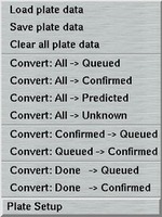
| Load plate data | Loads premeasured data from a crystallization plate, as produced by menu item "Save plate data" |
| Save plate data | Saves measured positions for all drops of the current crystallization plate. When saving the data, you will be asked for a file name. | |
| Clear all plate data | Clears all currently stored drop positions. Good idea to do this when mounting a new plate. The status of drops changes to "predicted". | |
| Convert: All → Queued | Defines all drops as "queued" - regardless of their previous state. The queue numbers start with pos. 1 as the upper right corner and is incremented sequentially. | |
| Convert: All → Confirmed | Defines all drops as "confirmed" - regardless of their previous state. | |
| Convert: All → Predicted | Defines all drops as "predicted" - regardless of their previous state. | |
| Convert: All → Unknown | Defines all drops as "unknown" - regardless of their previous state. All x,y-coordinates are lost. | |
| Convert: Confirmed → Queued | Puts all confirmed drops into the data collection queue, starting with pos. 1 as the upper right corner and incrementing sequentially. | |
| Convert: Queued → Confirmed | Opposite from above. Sequential numbers are removed. | |
| Convert: Done → Queued | After data have been collected from a queued drop, its status changes to 'done'. If you want to recollect data from all queued drops, here you can change them all to 'queued'. | |
| Convert: Done → Confirmed | Similar to above, but drops will not receive a queue number. | |
| Plate Setup | Opens the Crystallization Plate Setup window (see above). |
3. XPS Translations
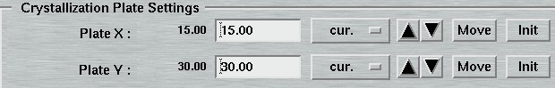
The Crystal Plate Scanner features 2 motors for x- and y-translations: XPS_X and XPS_Y. Both can be initialized at the "near end" of its translation stage by using the "Init" buttons in this area. Please note, that when seen from the X-ray source a positive translation of XPS_X tranlates the plate towards the left hand side with respect to the collimator. A positive translation of XPS_Y translates the plate upwards. When pushing the "Move" button, the selected motor is driving to the given position.
4. XPS Plate ID
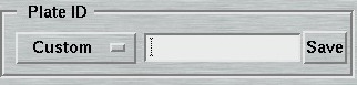
You may enter a specific identifier for your crystallization plate here. When pushing the "Save" button, the motor positions for all measured drops is being saved to file "Identifier.dat" in directory MARLOGDIR/xps. The ID string should not contain spaces and it also best to avoid special characters. Instead of using the "Custom" choice, the choices "Date", "Increment" and "Random" are available. For "Date", "Increment" and "Random", the input field on the right hand side of that menu is ignored. As ID string, either the current date and time ("Date") is used or a random string consisting of 3 alphanumeric characters ("Random") or a incremental number ("Increment").
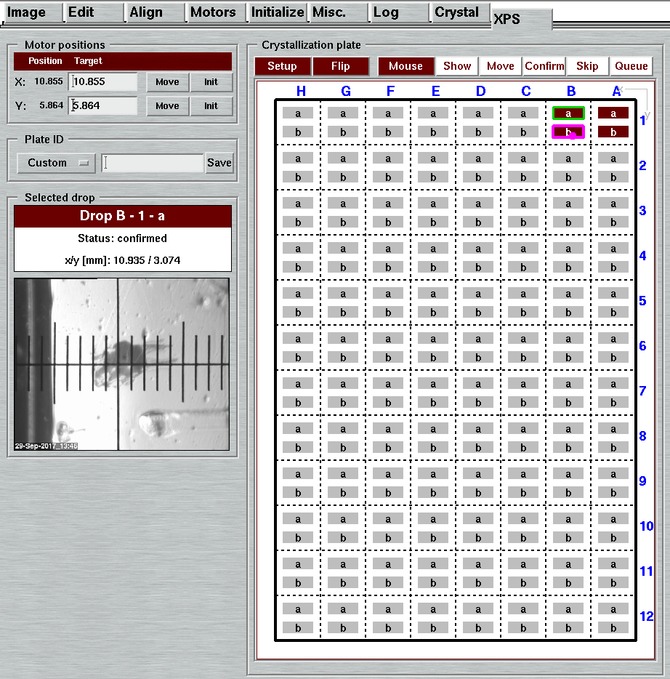
5. Selected drop
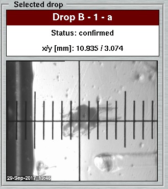
When clicking into a specific drop in the "Crystallization plate" area on the right hand side of the XPS page, relevant information for the selected drop is displayed separately in this area. Each drop may have a defined status: either "unknown", "predicted", "confirmed", "queued" or "done" (see below). For drops that have been confirmed, typically a photo is available (if a video grabber card is available on the PC) and that photo will be shown underneath the status area.
6. Crystallization plate
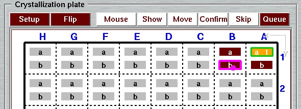
This area show the current setup of the crystallization plate as seen from the perspective of the X-ray beam leaving the collimator. Please note, that the visualization of the crystallization plate may not be identical to your actual crystallization plate. For simplicity, drops a to c are either shown in a strictly vertical arrangement (as shown above) or in a horizontal arrangement, but not in mixed arrangements like can be found for instance in Swissci 3-drop plates. Still, since the relevant parameters for moving from drop a to drop b and from drop b and drop c are part of the plate definitions, you can assume that when moving from drop a to drop c you may get close to where the expected crystal sits.
For further understanding, it is important that you understand that for all
drops in a given plate, a couple of specific states are defined and
marked by a color code:
- Unknown: No specific information available (white)
- Predicted: x,y-positions have been predicted (grey)
- Confirmed: x,y-positions have been explicitely confirmed (dark red)
- Queued: Drop has been queued for data collection (orange)
- Done: Drop has been used in data collection (green)
In the figure above you will also see 2 more features in drops and B1b:
- Green rectangle: currently selected drop
- Dot in magenta: marker for the current positions of XPS_X and XPS_Y
In the top area you will find some push
buttons with the following functions:
- Setup: Pops up the "Crystallization Setup" window when pushed. Here you have to define the physical properties of your type of crystallization plate.
- Flip: Every crystallization can be mounted in the XPS holder either with row 1 at the top or row 1 at the bottom. When pushing "Flip" the orientation is toggled. Please note, that when flipping the orientation, the previously determined x,y-coordinates for all drops become invalid, since the crystallization plate mounting is done manually and has some allowance for movements in either direction so remounting a plate always gives slightly different positions.
The next series of buttons is mutually exclusive. Only 1 choice can be active
at a time. They can be used to select drops and to perform specific operations.
- Mouse: When selected, the mouse buttons have different functions:
- Left: Single click: Show. Double click: Clear
- Middle: Confirm
- Right: Move
- Show: Show status of selected drop
- Move: Move x,y to selected drop. If the coordinates have already been confirmed, the stored values will be used. Otherwise, the target position is derived from geometrical parameters of the crystallization plate.
- Confirm: The current x,y-positions are "good", i.e. they can be used for a data collection. A confirmed drop is marked in red color. If a frame grabber is available on your PC, the software shoots a photo of the sample and stores it in directory MARLOGDIR/xps.
- Clear: Change the status of a drop to the preceding status, i.e.:
- Done → Queued
- Queued → Confirmed (all other queue positions remain as are)
- Confirmed → Predicted
- Predicted → Unknown
- Queue: Queueing refers to a sequence of drops that can be collected automatically during a data collection. Before being able to queue a drop, its motor position must have been confirmed. When a confirmed drop is queued, its color changes to orange. When a queued drop is selected again, it is being taken off from the queue and the color changes back to red. The numerical value in the drop indicates the position in the queue. The queue order is strictly sequential meaning that they receive their queue position from the order in which they are selected. If a queued drop at position #3 from 10 already queued positions is deselected, the remaining drops at position #4 to #10 are being moved one up. Currently, it is not implemented to insert a drop at a specific position in a queue. If you need a specific order, you will have to clear the queue and start over select drops exactly in the order you want them to be collected.
When a new plate is mounted, all previously established drop positions become useless. Since the XPS system does not know that a plate mounting has taken place, you have to manually tell the software that you want to start with a fresh plate by clearing all drops. This is most easily done by choosing the "Clear all drops" menu item in the XPS menu of the main window. Please note, that with this procedure really all existing x,y-positions for the drops and also all existing photos of confirmed drops will be replaced by predictions, unless you save them first in some other place.
When valid photos of confirmed positions are available, they will be shown in the status area (see above) when selecting the drop (in mode "Show").
WARNING: if you confirm a drop, always the current XPS_X and XPS_Y positions will be used for the selected drop.
7. Data Collection
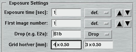
When collecting data with the crystal plate scanner mounted in place, moving the PHI axis is no longer possible. A data collection therefore typically consists of single exposures without further possibilities of movement. It is possible to start the data collection at the current position or to let the instrument drive to a given drop whose coordinates in x,y (i.e. positions for motors XPS_X and XPS_Y) have been established previously. Therefore, the "Exposure Settings" section of the "Edit"-page provides only input fields for exposure time and the starting image number as well as for the drop to measure. The drop field may be left empty, meaning that the XPS_X and XPS_Y will stay where they are.
If you enter a specific drop name, you have to stick to the nomenclature CNd where C is the column label (i.e. A-H), N is the row number (i.e. 1-12) and d is the drop label (i.e. a-c). The corresponding drop must be in state "confirmed", otherwise an error will be generated.
If you choose "Queue" in the option menu above, the data collection will automatically make single shots of all queued drops in the order as explained above.
The fields "Grid hor/ver" is a special feature that allows for automatically collecting a series of images around the [XPX_X,XPS_Y]-position of the selected drop. The input MUST be given in a specific form: N x stepsize, where N MUST be and odd number and stepsize is the translation in mm from one grid position to the next one. As an example, let us assume that drop B1b has stored coordinates at [20.0, 30.0] and a horizontal grid with 3 x 1.00 mm and a vertical grid with 3 x 0.5 mm is given, the program will produce 9 images at the following positions:
| X | Y | X | Y | X | Y | |||||
|---|---|---|---|---|---|---|---|---|---|---|
| 19.0 | 29.5 | 20.0 | 29.5 | 21.0 | 29.5 | |||||
| 19.0 | 30.0 | 20.0 | 30.0 | 21.0 | 30.0 | |||||
| 19.0 | 30.5 | 20.0 | 30.5 | 21.0 | 30.5 |
8. Crystal page
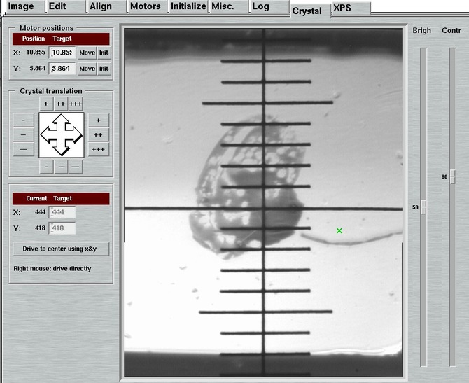
On the "Crystal"-page of the user interface, the layout changes slightly compared to a "normal" desktop beamline: the area with the camera view is rotated clockwise by 90 degrees in order to look at the crystal as the human eye would see it when looking in direction of the beam.
In the input area "Motor positions" you may enter specific values to drive XPS_X and XPS_Y or you may initialize those motors (close to 0.0). By pressing the buttons "+", "++", "+++", "-", "--" and "---" in the "Crystal translation area" you may move the plate left or right or up and down by fixed relative translations.
You may also use the right mouse button to point and click to a certain position in the video area and the motors XPS_X and XPS_Y are going to move the position that you clicked into the center of the cross-hair.
9. TV window
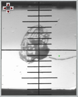
If you want to keep looking at the video camera while working on the "XPS"-page of the user interface you may select "TV window" from the "Video" menu at the top of main window. An additional window opens up that shows the video stream of the camera in the same way as on the "Crystal"-page.
The buttons in the upper left corner work of that window work somewhat differently, though. When pushed once, they start a continuous movement at a given (slow) speed. This movement will only come to an end when driving into an end-switch or some obstacle! When the motor is moving, the button will change its color to red and you may push it once more to interrupt the movement right away.
However, it is easier to use the "point and click"-method with the right mouse button to let the XPS_X and XPS_Y drive to the selected position.