GUI - Graphical User Interface
- 1. Basic Concepts
- 2. Environment
- 3. Command Line Options
- 4. User Interface
1. Basic Concepts
The program has to perform several tasks:
- Allow user input, i.e. setup data collection parameters, analyze images, etc.
- Send commands to the detector (e.g. mar345 Image Plate)
- Receive status information from the detector
- Send commands to the goniometer (desktop beamline)
- Receive status information from the goniometer
- Transform spiral images into Cartesian images (mar345dtb version)
- Display images
- With the optional sample changer: change crystals, center crystals
- With the optional crystal plate scanner: move from one well to another
Both the mar345-detector and the desktop beamline are driven by autonomous mini-computers which communicate with the host computer through an Ethernet interface. They feature a real-time operating system which provides the well known IP services (ftp, telnet, ping, Unix sockets). They come with a defined IP-address: 192.0.2.1 for the mar345-detector and 192.0.2.3 for the desktop beamline. Program mar345dtb talks to the scanner using standard Unix sockets on ports 4441, 4442, 4443 and 4444. In a similar way, the program uses ports 4451 to 4454 to communicate with the desktop beamline. An essential requirement for program mar345dtb to talk to both the detector and goniometer is a successful "ping" to IP-addresses 192.0.2.1 and 192.0.2.3, respectively. For this purpose, the host computer must be equipped with a dedicated Ethernet card set to IP-address 192.0.2.2. Detector, desktop beamline and host computer should be connected to a hub using standard RJ-45 cables.
The DECTRIS detectors also communicate with the mardtb program via network connections. PILATUS3 detectors use dedicated TCP/IP-sockets, EIGER detectors use a stateless RESTful interface for receiving commands and sending status and a special streamer interface for sending image data. Further technical details are not an issue in this document.
Transformation and data display requires memory as well as CPU-time. Typically, the program mar345dtb keeps the equivalent of 2.5 images in memory. When using images with 3450*3450 pixels, this corresponds to 75 MB. A minimum of 128 MB is therefore recommended for a host computer driving the detector, but 256 MB are actually more appropriate.
Data collection should always have highest priority. However, there is little protection against abuse of the host computer's resources by other processes. In particular, memory consuming data processing jobs can cause drops in performance of the workstation to such a degree that nothing else will work. I/O-operations can be even more critical. This affects network I/O, in particular.
Note: it is not advisable to write data out to an NFS-mounted disk since any problem on the network will affect data collection .
2. Environment
The program relies on a couple of predefined environment variables. The environment should best be defined within the shell startup scripts, i.e. files $HOME/.cshrc (C-shell) or $HOME/.tcshrc (TC-shell) or $HOME/.bashrc (Bourne-shell) using the corresponding syntax. The mar345dtb software distribution guide gives more details about how the mar software is organized. The official mar345dtb software distributions assumes that the default user's shell is the (t)csh. The following environment variables need to be declared:
Table 1: Environment variables
| Variable | Default value | Description |
|---|---|---|
| MARHOME | $HOME | Root directory for mar software distribution |
| MARTABLEDIR | $MARHOME/tables | Location of calibration and configuration files |
| MAR_SCANNER_NO | 000 | Three digits serial number for mar345 image plate scanner |
| DECTRIS_NO | 000 | Three digits serial number for DECTRIS detector in program mardtb. |
| MAR_DTB_NO | $MAR_SCANNER_NO | Three digits serial number for dtb. |
| MARLOGDIR | $MARHOME/log | Location of all log-output files and of data input files. The program mar345dtb expects to find subdirectories beam, log, lp, spy and sets. Very important: this directory must have write permission for the mar345dtb user! |
| MARHELPDIR or MARDOCDIR | $MARHOME/doc/ | Location of this html documentation |
The choice on how to set the environment variables depends on local
usage and personal preference. In particular, you will have to decide wether
you want to install the software in a location with general read access and
no write access. Thus, the software may be installed e.g. in
/usr/local/mar
with subdirectories
tables, doc, man, bin
and
log.
It is essential that the user has permission to write into $MARLOGDIR
and the following directories thereof:
- $MARLOGDIR/beam
- $MARLOGDIR/log
- $MARLOGDIR/lp
- $MARLOGDIR/spy
- $MARLOGDIR/sets
- $MARLOGDIR/csc (when used with sample changer or easymount)
- $MARLOGDIR/xps (when used with crystal plate scanner)
In cases, where program mardtb is to be used without mar345 scanner control but with DECTRIS detectors, the environment variable MAR_DTB_NO will be checked first, and only it is not defined DECTRIS_NO or MAR_SCANNER_NO will be used.
3. Command Line Options
Program mar(345)dtb can be invoked in a terminal window plainly by typing "mar345dtb" or "mardtb", respectively. The program however understands the command line options given in Table 2. Do not run the program in the background and do not use this terminal window for other purposes. The program will send important output to the standard output and you don't want to miss it, although almost all output can also be found in the log file.
At startup, the program will tell you something like:
mar345dtb: Version 9.0.0 (Mar 29 2009) by marxperts ...
mar345dtb: Connected to host '192.0.2.3' on port 4451 (COMM)
mar345dtb: Connected to host '192.0.2.3' on port 4452 (STAT)
mar345dtb: Connected to host '192.0.2.3' on port 4453 (DATA)
mar345dtb: Connected to host '192.0.2.3' on port 4451
mar345dtb: Connected to host '192.0.2.1' on port 4441 (COMM)
mar345dtb: Connected to host '192.0.2.1' on port 4442 (STAT)
mar345dtb: Connected to host '192.0.2.1' on port 4443 (DATA)
mar345dtb: Connected to host '192.0.2.1' on port 4441

=======================================================================
            Program            :  mar345dtb
            Version            :  9.0.0  (Mar 29 2009)
            Scanner S/N        :  001
            DTB     S/N        :  001
            Scanner mode       :  345 mm @ 0.15 mm
            Started on         :  Mon Mar 29 15:10:56 2009
            LOG  file is       :  /home/mar345/log/log/dtb.log.1
            STAT file is       :  /home/mar345/log/lp/mar.lp.1
=======================================================================
The program will also tell you if it is able to talk to the detector and to the desktop beamline. If environment variables are not set you will be notified.
At startup, the program writes information about connection success or failure into file $MARLOGDIR/mar.message. This message is read and displayed by program marstart which is called automatically by program mar345dtb. If the program cannot connect to either the detector or the dtb, the program mar345dtb will be halted. Program marstart then offers a choice of either killing process mar345dtb or continuing with program mar345dtb without network connection.
Note that it takes approx. 1 minute after turning on the mar345-detector and/or desktop beamline before program mar345dtb can talk to them, even if the ping service is available within a couple of seconds time.
After the initializations, the program presents essentially two windows:
an image display area and the mar345dtb main window with status
information and further input buttons.
Table 2: Command line options for mar345dtb
| Name | Alternative | Arguments | Example | Description |
|---|---|---|---|---|
| -dtb | -base | <string> <number> | -dtb 192.0.2.3 4451 | Host name and socket port for dtb. |
| -mar345 | -scan -det | <string> <number> | -mar345 192.0.2.1 4441 | Host name and socket port for mar345 scanner or DECTRIS detector. |
| -marmux | <string> <number> | -marmux 192.0.2.100 502 | Host name and socket port for marμX generator. | |
| --host | <string> | --host 192.0.2.3 | Host name to use for the dtb. | |
| -p | --port | <number> | -p 4451 | Socket port to use for the dtb. |
| --admin | Run program in administrator mode. | |||
| -c | --colors | <number> | -c 32 | No. of colors to use for image display. |
| -d | --default | <number> | -d 2300 | Default scan mode to use (one of 3450,3000,2400,2300,2000,1800,1600 or 1200). |
| --debug | <number> | --debug 16 | Debugging flag (undocumented). | |
| -g | --geometry | WxH[+x+y] | -g 900x600+320+200 | Specifies size [width x height] and location [+x+y] of the main window |
| --gear | <N> | --gear 0 | Force gear N for exposures. N=0,1,2,3,4 Depends on time and dphi. | |
| -h | --help | Print usage summary | ||
| -i | --init | <number> | -i 11 (=1+2+8) | Hexcode for commands to execute at startup: 0x01 = set time and date inside controllers 0x02 = get firmware version 0x04 = close shutter 0x08 = adjust ADC offsets 0x10 = turn on high voltage 0x20 = lock image plate 0x40 = apply a button mask to the remote control unit 0x80 = tell CSC to operate at cryo conditions 0x100 = tell CSC to operate at room temperature |
| +minmax | Prevent user from entering motor target values into user interface that exceed min. and maximum values as provided in the mardtb configuration file. | |||
| -n | --nodisp | Don't pop up the image display window at start of program. | ||
| --noicon | Prevents usage of color icons (to save colors, see --nodisp). | |||
| --nodtb | Start program without opening connection to dtb. | |||
| --no345 /--nodet / +345 | Start program with(out) opening connection to detector (overrides entries in configuration file). | |||
| --nocsc | Start program without sample changer support (overrides entries in configuration file). | |||
| --nomarmux / +marmux | Start program with(out) marμX support (overrides entries in configuration file). | |||
| --novideo | Start program without video support (overrides entries in configuration file). | |||
| <string> | --print TASK --print CAN 11 | Print additional status block information: TASK = print all changes in task status DIO = print all changes in digital I/O bits ADC = print all ADC value readings ERROR = print all error numbers in status block CAN <number> = print all bits for CAN-motor number | ||
| --rev | Reverse direction of PHI axis | |||
| -s | --server | <PORT> | -s 3450 | Listen for commands on PORT |
| -v | --verbose | Increase printed output. No arguments. | ||
| --xps / ++xps | Start program with(out) crystal plate scanner support (overrides entries in configuration file). | |||
4. User Interface
The user interface features 2 windows
(Main Window and a
Status Window) with a summary of the current activities.
4.1 "Main" Window
The main window controls all detector and goniometer functions. It comes in a "notebook" style with a number of pages and subsections. If the first place it consists of two areas:
- menu bar
- notebook containing several pages with tabs for navigation

4.1.1 Menu Bar
The menu bar allows for opening additional windows. Most of them
can be opened either by selecting the corresponding choice with the
mouse button or by pressing the corresponding short-cut key.
Some of the windows can also be opened by pressing the status buttons
or control buttons (see below).
4.1.1.1 File Menu
The File menu pops up if the "File" button in the menu bar is pressed or if "Alt+f" is pressed while the pointer is in the main window. Most of the choices in the menu (Ctrl+0 to Ctrl+9 ) will allow to navigate from page to page in order to access specific functions:
| Menu | Menu Choice | Shortcut | Description |
|---|---|---|---|
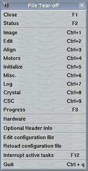
| Close | F1 | Closes the main window and pops up the status window |
| Status | F2 | Pops up the status window | |
| Image | Ctrl+1 | Switches to page for image display | |
| Edit | Ctrl+2 | Switches to page for editing data collection params | |
| Align | Ctrl+3 | Switches to page for dtb alignment | |
| Motors | Ctrl+4 | Switches to page for driving dtb motors | |
| Initialize | Ctrl+5 | Switches to page for initializing dtb motors | |
| Misc. | Ctrl+6 | Switches to page for misc. purposes | |
| Log | Ctrl+7 | Switches to page for log messages | |
| Crystal | Ctrl+8 | Switches to page for crystal display and centering | |
| CSC | easymount | Ctrl+9 | Switches to page for sample changer or easymount operations | |
| marμX | Switches to page for marmux generator operations | ||
| metaljet | Switches to page for metaljet generator operations (not shown here) | ||
| Progress | F3 | Monitors progress and status of current data collection | |
| Hardware | Switches to page for monitoring hardware activity | ||
| Optional Header Info | Pops up a window where some values may be edited that go into image file headers | ||
| Administrator | Pops up a window where motor positions can be redefined. Only available when running the program in administrator mode (option --admin) | ||
| Edit configuration file | Calls editor and loads the configuration file | ||
| Reload configuration file | Reload params from configuration file | ||
| Interrupt active tasks | Emergency stop for any activity | ||
| Quit | Ctrl+q | Leave program mar345dtb |
4.1.1.2 Edit Menu
The Edit menu pops up if the "Edit" button in the menu bar is pressed or if "Alt+e" is pressed while the pointer is in the main window. The separate chapter "Edit" describes this menu.
4.1.1.3 Align Menu
The Algin menu pops up if the "Align" button in the menu bar is pressed or if "Alt+a" is pressed while the pointer is in the main window. The separate chapter "Align" describes this menu.
4.1.1.4 Image Menu
The Image menu pops up if the "Image" button in the menu bar is pressed or if "Alt+i" is pressed while the pointer is in the main window. The separate chapter "Image" describes this menu.
4.1.1.5 Video Menu
The Video menu pops up if the "Video" button in the menu bar is pressed or if "Alt+v" is pressed while the pointer is in the main window. The separate chapter "Crystal" describes this menu.
4.1.1.6 CSC Menu
The CSC menu pops up if the "CSC" button in the menu bar is pressed or if "Alt+c" is pressed while the pointer is in the main window. The separate chapter "CSC" describes this menu.
4.1.1.7 XPS Menu
The XPS menu pops up if the "XPS" button in the menu bar is pressed or if "Alt+x" is pressed while the pointer is in the main window. The separate chapter "XPS" describes this menu.
4.1.1.8 Help Menu
The Help menu pops up if the "Help" button in the menu bar is pressed or if "Alt+h" is pressed while the pointer is in the main window.
| Menu | Menu Choice | Description |
|---|---|---|

| Contents | Calls the WWW-browser and loads file $MARDOCDIR/mar345dtb.htm |
| About | Shows current program version |
4.1.2 Pages
In the following sections the individual pages of the main window will be described in more detail.
4.1.2.1 Image
The "Image"-page can be accessed by selecting the corresponding choice in the "File"-menu or by pressing the "Ctrl+1"-keys while the pointer is in the main window. This page is the area where to visually inspect images. The separate chapter "Image" describes the functionality of this window.
4.1.2.2 Edit
The "Edit"-page can be accessed by selecting the corresponding choice in the "File"-menu, by pressing the "Ctrl+2"-keys while the pointer is in the main window. Here, you set all the parameters for one or more data collection runs. The separate chapter "Edit Data Collection Parameters" describes the functionality of this page.
4.1.2.3 Align
The "Align"-page can be accessed by selecting the corresponding choice in the "File"-menu, by pressing the "Ctrl+3"-keys while the pointer is in the main window. This window is the area where to align the desktop beamline with the X-ray beam. The principles of alignment are described in chapter "Principles of Operation" of the Introduction. The separate chapter "Align" describes the functionality of this page.
4.1.2.4 Motors
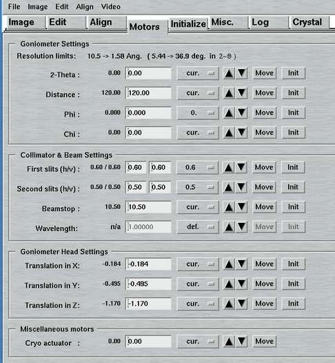
The "Motors"-page can be accessed by selecting the corresponding choice in the "File"-menu or by pressing the "Ctrl+4"-key while the pointer is in the main window or by pressing any of the motor status buttons in the status window. You can move single motors by pressing one of the motor buttons on the right hand side of the window. The option menues offer several useful choices. The choice "cur." will write the current motor reading into the corresponding text field. Note that the horizontal and vertical slits will both move to the desired positions. If the target position does not differ from the current position, there will be no action.
For most installations, the "Wavelength" is not really a movable motor but it can be configured as such.
4.1.2.5 Initialize
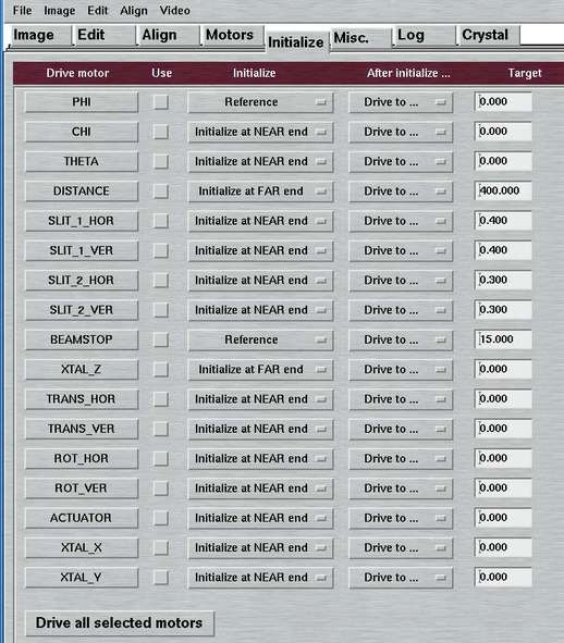
The "Initialize"-page can be accessed by selecting the corresponding choice in the "File"-menu or by pressing the "Ctrl+5"-key while the pointer is in the main window. You can initialize single motors by pressing one of the motor buttons on the left hand side of the window. Otherwise, you can select the "Use"-button of the desired motors and press the "Drive all selected motors"-button at the bottom of the window to initialize all selected motors. The actual initialization procedure may be followed by another action, typically by driving to a default value.
All motors of the dtb (see Table 1.2) can be initialized to a defined (i.e. calibrated) position. The mechanism of initialization may differ from motor to motor, though. Most motors carry sensors (light gaps) at both ends of their translation stages. There are dedicated hardware commands to tell the motors the calibrated positions when driving into these sensors. In principle, all of these motors could be referenced at either the "NEAR" end or the "FAR" end of their translation stage. For some motors, the initialization will be restricted to only one choice via the configuration file (see chapter Configuration File in section Input). In particular, the DISTANCE initialization at the "NEAR" end - close to the crystal - imposes certain risks to drive the detector into some obstacle, e.g. the beamstop, cryostream, etc.. It is therefore useful, to initialize the DISTANCE motor at the "FAR" end only, i.e. at the back of the translation stage. Similarly, it does not make too much sense to initialize the 2-theta arm at beyond 30 degrees of rotation but only close to 0!
The PHI and BEAMSTOP motors have a different way of referencing. They have only one sensor. In the case of PHI this sensor sits close to the 0 reading on the hand dial. The sensor for the beamstop sits about 18 mm away from the crystal.
The four slit motors don't have any sensor at all and hence no physical feedback of the correctness of the motor readings. The initialization is done by driving the slits to the minimum. This is physically less than 0.0 mm. Note, that the slits will be slightly open at negative slit readings and will be entirely closed only if they are at 0.00 mm. The exact positions are calibrated in the factory.
The dtb-controller stores all motor positions in static memory,
so the motor positions are not lost if the power is cutoff. It is therefore
not necessary to initialize the motors regularly. It is only required
during installation and after a replacement of the dtb-controller.
Motors cannot be moved manually except the following:
- PHI
- CRYSTAL (PHI-translation)
- BEAMSTOP
- SLITS (hor. and ver. for ion. chambers 1 and 2)
When moved manually, the motor positions stored by the controller don't coincide any more with the actual positions. For the PHI-axis things are less critical since the PHI-axis has to be returned to its "locked" state which is a unique position in the full turn. Otherwise, the PHI-axis will not move properly at all. But for the slits and for the beamstop it will be important, that during data collection they are physically at the correct positions. We therefore recommend:
- Reference the BEAMSTOP and CRYSTAL translation every time you start working with the instrument. Do this before mounting the goniometer and crystal.
- Check SLITS, i.e. check wether the dial readings on the 4 slits correspond to the values of the slits shown in the user interface. If not, manually set the dials to the values displayed by the software.
4.1.2.6 Misc.
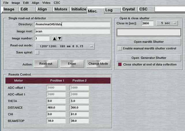
The "Misc."-page can be accessed by selecting the corresponding choice in the "File"-menu, by pressing the "Ctrl+6"-key while the pointer is in the main window, or by pressing the "Scanmode"-or "Shutter"-button in the status window.
This page offers 3 different functions:
- Single read-out or erase of the detector
- Open/close shutter(s)
- Settings for the remote control unit
4.1.2.6.1 Single scan
Here, you may select a directory, image name, image number and scanmode and choose an action. You may:
- Scan the plate, i.e. make a single read-out and store data to disk
- Erase the plate, i.e. make a scan without actually storing the data
- Change mode, i.e. drive the scanning head inside the detector to the choosen scanmode and load the corresponding speed profiles.
This feature is not used very often unless for very special experiments. This is why this window is accessible only via one button. For producing an output file, there is no choice of format. Images will always be produced in the mar345-format that is described elsewhere. The output file name follows the same rule as described in the chapter about the data collection.
4.1.2.6.2 Shutter
Here, you may manually open the experimental beam shutter of the dtb without having to setup an exposure. It should be noted that for normal users there is little need to do so. When opening the shutter, there will be a clock showing the time elapsed since opening the shutter. The shutter will automatically closed after the time given in the "Close in [sec]" text field has elapsed .
Only if the "Enable manual shutter control" button is checked, the little switch for operating the X-ray shutter on the desktop beamline itself is functional. If this is enabled, the software will loose control over the shutter and won't gain it back until this button is unchecked!
If the option "USE TTL" is set in the configuration file
(see chapter
Configuration File in section
Input),
you will have an option to use the mar345 controller to open or close
a generator shutter using the shutter TTL signal of the mar345 scanner.
Obviously, the generator shutter has to be wired accordingly. If the
hardware is properly connected, you can open and close the generator
shutter using the push button. You also have a choice of automatically
closing the generator shutter at the end of a data collection. This
is a useful thing to do both for safety reasons as well as for increased
lifetime of the multi-layer mirrors.
4.1.2.6.3 Remote Control
Here, you can select choices concerning the behaviour of the optional Remote Control. For these choices to become relevant, the remote control obviously needs to be connected to the dtb. The window allows you to provide the following parameters by pressing the ENTER-key in the corresponding textfield.
- Alternate positions for driving the 2-theta arm
- Alternate positions for driving the detector distance
- Alternate positions for driving the CHI circle
- Alternate positions for driving the beamstop
The behaviour of the "Remote Control"-window can be controlled
by keywords in the configuration file
(see chapter
Configuration File in section
Input). Thus, it is possible to prevent input
of values in the textfields.
To provide suitable parameters, an understanding of the functionality of the remote control is required. Please refer to chapter 2.1.4 Remote Control Unit in section Introduction) for more details.
4.1.2.7 Log
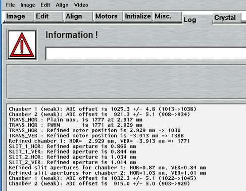
The "Log"-page can be accessed by selecting the corresponding choice in the "File"-menu by pressing the "Ctrl+7"-key while the pointer is in the main window, or by selecting the corresponding tab in the main window. All hardware errors and warning as well as some additional information may be written inside the text area of this window. Among others also the final results of alignment procedures ("Find Beam", "Optimize Beam", "Shape Beam") will be printed in this window.
In case of hardware problems, first have a look inside this window to get some history of the problem.
4.1.2.8 Crystal
The "Crystal"-page can be accessed by selecting the corresponding choice in the "File"-menu, by pressing the "Ctrl+8"-keys while the pointer is in the main window, or by selecting the corresponding tab in the main window. Here, you set all the parameters for one or more data collection runs. The separate chapter "Crystal" describes the functionality of this page.
4.1.2.9 Easy
The "Easy"-page can be accessed by selecting the corresponding choice in the "File"-menu, by pressing the "Ctrl+9"-keys while the pointer is in the main window, or by selecting the corresponding tab in the main window. Here, you can operate the functions of the "easymount" sample changer, if the mardtb goniostat is equipped with this optional functionality. The separate chapter "Easymount" describes the functionality of this page.
4.1.2.10 CSC
The "CSC"-page can be accessed by selecting the corresponding choice in the "File"-menu, by pressing the "Ctrl+9"-keys while the pointer is in the main window, or by selecting the corresponding tab in the main window. Here, you can operate the functions of the cryogenic sample changer, if the mardtb goniostat is equipped with this optional functionality. The separate chapter "Cryogenic Sample Changer" describes the functionality of this page.
4.1.2.11 marμX / MetalJet
The "marμX"-page or "MetalJet"-page can be accessed by selecting the corresponding choice in the "File"-menu or by selecting the corresponding tab in the main window. Here, you can operate the functions of the marμX or MetalJet X-ray source, like opening or closing X-ray shutters, etc. The separate chapters "marμX" and "metaljet" describe the functionality of these pages.
4.1.2.12 XPS
The "XPS"-page can be accessed by selecting the corresponding tab in the main window. Here, you set all the parameters for one or more data collection runs. The separate chapter "Crystal Plate Scanner" describes the functionality of this page.
4.1.3 Other Windows
4.1.3.1 "Progress" Window
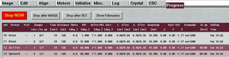
The "Progress"-window can be accessed by selecting the corresponding choice in the "File"-menu or by pressing the "F3"-key while the pointer is in the main window.
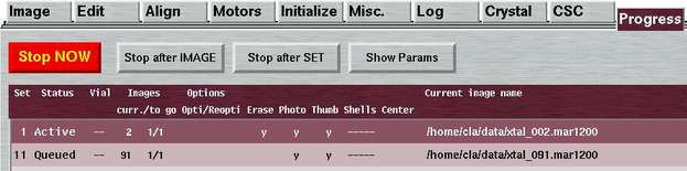
Here, you see the most important parameters of ongoing or programmed data collection runs. The window is opened automatically after pressing the "Go" button in the "Edit Data Collection"-window and before actually starting with a data collection. Since there is quite a large number of parameters that need to be listed, the window comes in 2 layouts that can be toggled on the fly by pressing the "Show Filenames"-button (which then says "Show Params""). On the first page ('Params'), you can see the crystallographic parameters, on the second page ('Filenames') the image file names and some additional options.
The data set that is currently active is marked in "mar" red and white fonts, the queued ones are shown with a lighter background. The ones that are already finished are drawn with a grey background. In this window you will also find the time the data collection needs to complete and the actual ending time.
Table 5a: The columns in the 'Params' section of "Progress"-window
| Name | Description |
|---|---|
| Set | Data set as programmed in the "Edit ..." window. |
| Status | Either "Active", "Queued" or "Done" |
| Vial | When using the sample changer, the selected carousel position is shown. |
| Image curr./to go | No. of current image followed by no. of remaining images out of total no. of images in this set. If set is not active, the current image equals to the starting image. |
| Time | Exposure time in seconds. When working in DOSE mode, the time will be only approximated. |
| Distance | The distance detector-to-sample in mm. |
| Theta | The 2-theta angle in deg. |
| Phi | The Phi at start of the current image in deg. |
| Delta-Phi | The no. of oscillations * Delta-Phi in deg. |
| Phi-inc | Phi-increment in deg., i.e. amount of Phi to be driven inbetween 2 consecutive images. |
| 1.slits | Horizontal and vertical slit apertures in 1. chamber in mm. |
| 2.slits | Horizontal and vertical slit apertures in 2. chamber in mm. |
| Beamstop | Distance beamstop-to-sample in mm. |
| Xtal-XYZ | Crystal xyz-translations of the goniometer head in mm |
| Format & Scanmode | The shown string is the actual image name extension and corresponds to the choices for "Format" and "Scanmode" in the "Edit..."-window. |
| To go | Time in hrs to terminate this set. |
| Ending time | Time when this data set completes. |
Table 5b: The columns in the 'Filenames' section of "Progress"-window
| Name | Description |
|---|---|
| Set | Data set as programmed in the "Edit ..." window. |
| Status | Either "Active", "Queued" or "Done" |
| Vial | When using the sample changer, the selected carousel position is shown. |
| Image curr./to go | No. of current image followed by no. of remaining images out of total no. of images in this set. If set is not active, the current image equals to the starting image. |
| Options | Shows selected options of the toggle buttons in the Edit window. |
| Current image name | Full path name of current image (or first image in set). |
The buttons in the lower part of the window are mostly self-explanatory. Some of the buttons will be made insensitive during certain operations. For instance, during a readout of the detector, the "Stop NOW"-button is disabled.
IMPORTANT HINT for using "Stop NOW":
Under certain conditions - e.g. when driving a motor in an endswitch -
it is possible that all major action buttons are disabled and you don't
seem to have a possibility to go on with your work. In this situation, it
usually helps
to press the "Stop NOW"-button (or the F12-key) to reenable
all buttons instead of restarting the program.
Table 6: The buttons in the "Progress"-window
| Name | Description |
|---|---|
| Go | Start data collection of all programmed sets. This button is enabled only before starting a data collection. |
| Stop NOW | Immediately abort the exposure or any motor movement. |
| Stop after IMAGE | Stop data collection of all data sets after finishing exposure and
readout of current image. When pressed, this button toggles with "Continue after IMAGE", so there is a chance to revert this action. |
| Stop after SET | Stop data collection of all queued data sets after finishing the
current set. When pressed, this button toggles with "Continue after SET", so there is a chance to revert this action. |
| Change Params | Returns to the "Edit Data Collection Parameters"-window. This button is enabled only before starting a data collection. |
| Close | Closes this window. Get this window back with the "F2"-key. |
4.1.3.2 "Image Header Info" Window
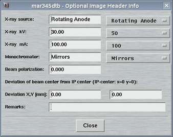
The "Image Header Info"-window can be accessed by selecting the corresponding choice in the "File"-menu of the main window.
Here, you can provide some information that is going to end up in the headers of images created by the mar345-detector. This information is strictly optional and there are no programs that are systematically making use of it. It would be good practice, though, to fill in the fields. A general experience is, that when working with images later you will have trouble to find notes written in a logbook, but it is straightforward to just look into the image header (e.g. with program catmar).
4.1.3.3 "Administrator" Window
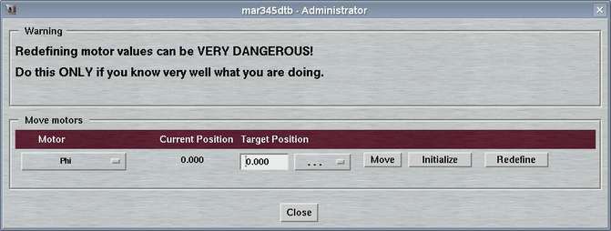
The "Administrator"-window can be accessed by selecting the corresponding choice in the "File"-menu of the main window.
Here, you can redefine motor positions. This is a dangerous thing to do and normally there should not be a necessity at all to do so. This is why the choice for opening this window only is available when running the program in "administrator" mode. This mode requires to start the program with command line option "--admin".
4.1.3.4 "Hardware" Window
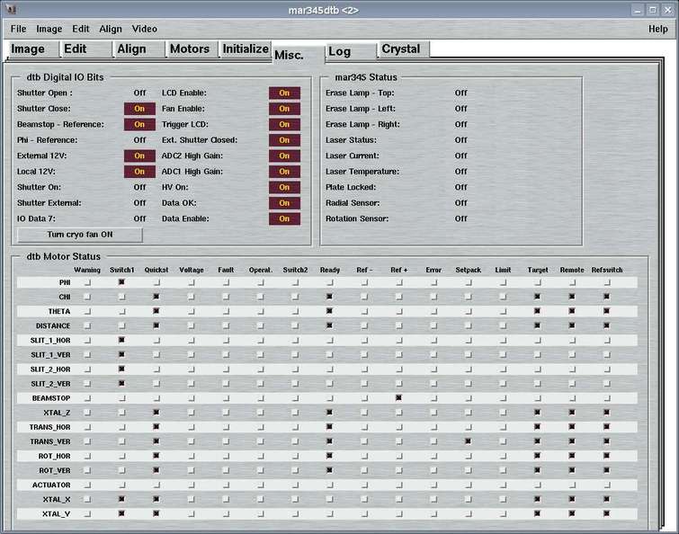
The "Hardware"-page can be accessed by selecting the corresponding choice in the "File"-menu.
Here, you can look at certain hardware bits in detail. The information presented here reflects the contents of the status block that is periodically sent by the dtb-controller to the computer.
The window features 3 areas:
- dtb Digitial IO Bits:
This area looks at some single hardware bits, among others the status of the local X-ray shutter. Note, that for safety reasons the state of the X-ray shutter is controlled by 2 independent sensors: one that checks wether the shutter is open and one that checks wether the shutter is closed. For increased safety, the state "shutter is closed" is true only if both bits "Shutter Close" is "On" (i.e. true) and "Shutter Open" if "Off" (i.e. false).On the bottom of this area you will find a button that allows you to toggle the operation of the fan of the cryo exhaust. If the dtb is powered on, this fan is turned on as well. With the potentiometer on the fan you can't turn it off completely but only with the help of this button!
- mar345 Status:
This area looks at some information from the mar345 image plate detector. The entries should be self-explanatory. Watch the bits as they change state during a scan... - dtb Motor Status:
This area reflects the information of single motor modules on the CAN-bus. Technically, all motors carry a 16-bit status word. Not all of the 16-bits are used. Here you can detect wether a motor hits an end switch, wether a motor is moving at all or wether it is idle. The description of all of the 16 bits would be too much detail.Note that the 4 slit motors, PHI and BEAMSTOP behave differently from all others. This is because those motor modules physically sit on the dtb-controller card, while all other motors have their own hardware modules.
4.2 "Status" Window
The status window monitors all detector and goniometer activity and displays current motor positions, the shutter state, X-ray intensity readings, etc. If the first place it consists of two areas:
- menu bar
- fields displaying status information
4.2.1 Menu Bar
4.2.1.1 File Menu
The File menu pops up if the "File" button in the menu bar is pressed or if "Alt+f" is pressed while the pointer is in the status window. Most of the choices in the menu (Ctrl+0 to Ctrl+9 ) will allow to navigate from page to page in order to access specific functions:
| Menu | Menu Choice | Shortcut | Description |
|---|---|---|---|
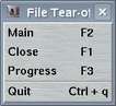
| Close | F1 | Closes the status window and pops up the main window |
| Main | F2 | Pops up the main window | |
| Progress | F3 | Monitors progress and status of current data collection | |
| Quit | Ctrl+q | Leave program mar345dtb |
4.2.1.2 Help Menu
The Help menu pops up if the "Help" button in the menu bar is pressed or if "Alt+h" is pressed while the pointer is in the main window.
| Menu | Menu Choice | Description |
|---|---|---|
|
| Contents | Calls the WWW-browser and loads file $MARDOCDIR/mar345dtb.htm |
| About | Shows current program version |
4.2.2 Status Fields
Most of the status buttons have double functionality: they display current status (e.g. motor positions) and they can be pushed to pop up additional windows:
| Button | Button | Action when pressed | Description |
|---|---|---|---|
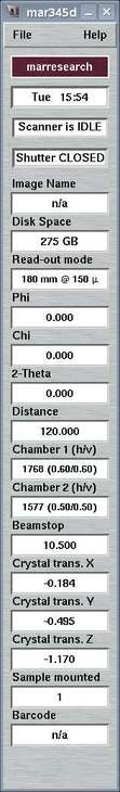
| marxperts | none | Shows ending time during data collection |
| Mon 15:30 | none | Current computer time | |
| Scanner is IDLE | none | Current dtb or detector action (progress bar) | |
| Shutter CLOSED | Pops up the "Misc."-page in the main window | Shows current state of experimental beam shutter. | |
| Image Name | Pops up file selection window | Displays current image name during data collection | |
| Disk Space | Pops up file selection window | Displays remaining disk space in current data directory | |
| Scanmode | Pops up the "Misc."-page in the main window | Displays current scan mode of mar345-detector | |
| Phi | Pops up the "Motors"-page in the main window | Displays current PHI position | |
| Chi | Pops up the "Motors"-page in the main window | Displays current CHI position (Phi-swing) | |
| 2-Theta | Pops up the "Motors"-page in the main window | Displays current 2-Theta position | |
| Distance | Pops up the "Motors"-page in the main window | Displays current distance detector to crystal | |
| Chamber 1 (h/v) | Pops up the "Motors"-page in the main window | Displays current reading of 1. ion. chamber and positions of hor. and ver. slits | |
| Chamber 2 (h/v) | Pops up the "Motors"-page in the main window | Displays current reading of 2. ion. chamber and positions of hor. and ver. slits | |
| Beamstop | Pops up the "Motors"-page in the main window | Displays current beamstop position | |
| Crystal trans. X | Pops up the "Motors"-page in the main window | Displays current position of crystal x-translation | |
| Crystal trans. Y | Pops up the "Motors"-page in the main window | Displays current position of crystal y-translation | |
| Crystal trans. Z | Pops up the "Motors"-page in the main window | Displays current position of crystal translation along Phi-axis | |
| Sample mounted | Pops up the "CSC"-page in the main window | Displays vial no. of currently mounted sample | |
| Barcode | Pops up the "CSC"-page in the main window | Displays barcode of currently mounted sample |
If the option "USE TTL" is set in the configuration file or when using
the marμX generator within the mar345dtb program,
(see chapter
Configuration File in section
Input), instead of the "Disk space" field, there
will be a status indicator for the generator shutter.