Edit Data Collection Parameters
- 1. Introduction
- 2. Edit Menu
- 3. Selecting Data Sets
- 4. Directories, Names and Formats
- 5. Exposure Settings
- 6. Goniometer Settings
- 7. Collimator and Beam Settings
- 8. Options
- 9. Using Shell Commands
- 10. Sample Changer Settings
- 11. Crystal Plate Scanner Settings
1. Introduction
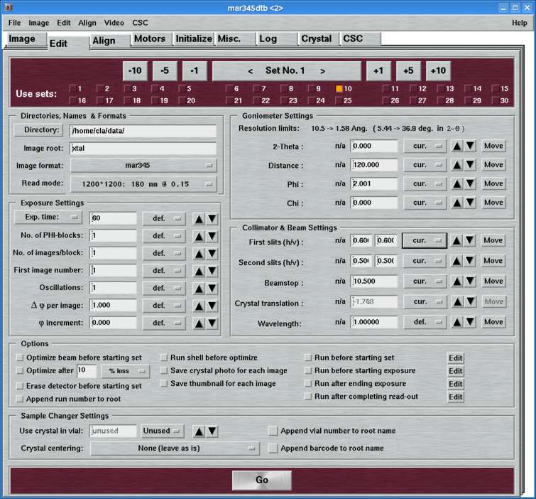
The "Edit"-page can be accessed by selecting the corresponding tab in the main window or by pressing the "Ctrl+3"-key while the pointer is in the main window. Here, you set all the parameters for one or more data collection runs.
The "Edit"-page features several work areas:
- a menu bar with various options(see 2.)
- an area for selecting sets to be programmed (see 3.)
- a parameter input area for directories, names and formats (see 4.)
- a parameter input area for exposure settings (see 5.)
- a parameter input area for goniometer settings (see 6.)
- a parameter input area for collimator and beam settings (see 7.)
- a parameter input area for options (see 8.)
- a parameter input area for external shell commands(see 9.)
- a parameter input area for sample changer settings(see 10.)
The window comes in 2 different layouts that can be easily be toggled with a single key stroke (Ctrl+a) or by (de-)selecting the choice "Use advanced features" in the "Edit"-menu of the menubar. The advanced features comprise the following input elements in addition to the "simple" features:
- Exposure settings:
- No. of PHI-blocks:
Possibility of setting up a MAD data collection run (see below) - Phi increment:
Possibility of using a Phi-movement inbetween 2 contiguous images of a data set
- No. of PHI-blocks:
- Goniometer settings:
- Chi:
Possibility of driving CHI (Phi-swing)
- Chi:
- Collimator settings:
- Slit, beamstop, crystal translations, wavelength:
Possibility of using different positions for all motors in this area for each data set.
- Slit, beamstop, crystal translations, wavelength:
- Options:
- Shell commands:
Option for running external shell commands during a data collection.
- Shell commands:
- Sample changer settings:
- Change crystal, center crystal, etc.:
When making use of the sample changer, using the "advanced features" is mandatory!
- Change crystal, center crystal, etc.:
2. Edit Menu
2.1 Description
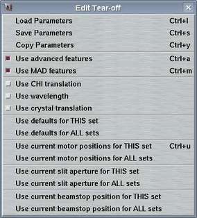
The "Edit"-menu pops up if the "Edit"-button in the menu bar is pressed or if "Alt+e" is pressed while the pointer is in the main window. This menu allows for accessing different options that have to do with data collection parameters. The choices are:
| Menu | Menu Choice | Shortcut | Description |
|---|---|---|---|
| Load Parameters | Ctrl+l | Opens "Load parameters"-window |
| Save Parameters | Ctrl+s | Opens "Save parameters"-window | |
| Copy Parameters | Ctrl+y | Opens "Copy parameters"-window | |
| Use advanced features | Ctrl+a | Toggles between "advanced" and "simple" layout of the "Edit..."-page | |
| Use crystal translation | Usually, there is no need to translate a crystal from the "Edit..."-page. It can always be done from the "Motor"-page. Still, the buttons can be enabled or disabled on the fly. | ||
| Use defaults for THIS set | Updates all parameter fields of current set with default values | ||
| Use defaults for ALL set | Updates all parameter fields of all sets with default values | ||
| Use current positions for THIS set | Ctrl+u | Updates all motor fields of current set with current motor positions | |
| Use current positions for ALL sets | Updates all motor fields of ALL sets with current motor positions | ||
| Use current slit aperture for THIS set | Updates slit fields of current set with current slit apertures | ||
| Use current slit aperture for ALL sets | Updates slit fields of ALL sets with current slit apertures | ||
| Use current beamstop position for THIS set | Updates beamstop field of current set with current beamstop position | ||
| Use current beamstop position for ALL sets | Updates beamstop field of ALL sets with current beamstop position |
NOTE:
The motor update options are convenient since it can save you a lot of typing.
The common situation is that you don't want to have varying slit sizes and
you don't move the beamstop inbetween data sets. So those options allow for
very easily setting the same parameters for all sets.
The option of updating all motor position fields should be used with
somewhat more care. Usage of this option implies, that the phi, distance,
and 2-theta settings will be updated together with those of the collimator
motors. When choosing to use defaults for the current or all sets,
motor parameters default to the current position.
2.2 Load Parameters
The "Load Parameters"-window can be accessed by selecting the
corresponding choice in the "Edit"-menu
or by pressing the "Ctrl+l"-key while the pointer is in the
main window.
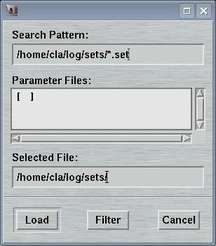
This window is used to select a file with data collection parameters. The format of this file is described in chapter Parameter File of section Input. This feature comes handy for loading parameters typically used for collecting data of a certain sample and saves you lots of typing.
The default place where to store and to load parameter files from is $MARLOGDIR/sets
2.3 Save Parameters
The "Save Parameters"-window can be accessed by selecting the
corresponding choice in the "Edit"-menu
or by pressing the "Ctrl+s"-key while the pointer is in the
main window.
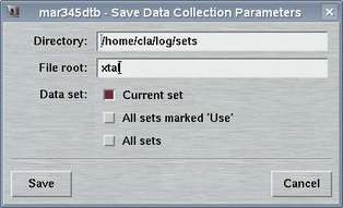
This window is used to store parameters from your current program session. You may may either save only the set that is currently in work or all sets at once. The format of this file is described in chapter Parameter File of section Input.
The default place where to store and to load parameter files from is $MARLOGDIR/sets
2.4 Copy Parameters
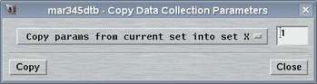
The "Copy Parameters"-window can be accessed by selecting the
corresponding choice in the "Edit"-menu
or by pressing the "Ctrl+c"-key while the pointer is in the
main window.
This window is used copy parameters from one data set into another data set. You may either copy parameters from current set into any other or copy parameters from any set into the current. This methods allows for quickly program multiple data sets with almost identical conditions.
3. Selecting Data Sets

The program allows for programming up to 30 data sets that can be run automatically in sequence. The large blue button in the center of this area tells you which data set you are currently editing. This button has double functionality: by pressing the button on the right hand side you move to next data set, by pressing the button on the left hand side you move to the previous data set. This is identical to pressing the +1 and -1 buttons, respectively. To scroll faster forwards and backwards there are additional buttons that allow you to move on in units of 5 and 10.
For a data set to be actually used you have to explicitely select the corresponding entry in the next 1 or 2 rows. The idea is that you can program a couple of data sets but you don't necessarily want to use them all the time. If there is no data set selected at all and you press the "Go"-button, the first data set only is going to be used.
In the configuration file (see chapter Configuration File in section Input). there is a possibility to restrict the number of programmable sets to 15, which should certainly be enough for home use.
For convenience, you can copy all parameters from one data set into another data set and save some typing. Please refer to chapter 2.4 (Copy Parameters). You can also load and store entire parameter sets for your current project (chapters 2.2 (Load Parameters) and 2.3 (Save Parameters). This is useful if you have a particular way of collecting data from a crystal.
4. Directories, Names and Formats
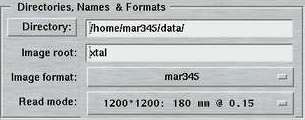
The entries of this area are identical for both "advanced" and "standard" layouts. Here is where you specify the place where the images are being stored, the image root names, formats and scan modes.
By pressing the "Directory"-button a file selection box pops up. It lists the files in the current directory. If you move up or down the directory tree inside this file selection box, the full directory path is entered automatically into the directory field and saves you from typing.
The "Image root" name should be some meaningful string that should allow you to identify your data later on in some way. Usage of blanks or special characters inside the textfield is possible but strongly discouraged.
The "Image format" allows to choose between several output formats, depending on program configuration. When used with the mar345 image plate detector, there is a choice of the mar345 file format, the cbf file format and a raw image file format of plain 16-bit data without header. When used with the DECTRIS detectors, a 32-bit TIFF format is offered as an additional choice. The mar345 formats have been introduced in 1997 and are supported by all major data processing and display programs (automar, marView, denzo, xdisp, mosflm, xds, fit2d, etc.). The cbf file format ("crystallographic binary format") is the definition of a general image data format for the crystallographic community following the CIF-standard as far as headers are concerned. Within CBF, different compression schemes and header flexible header arrangements are available. Hence, the CBF-output for DECTRIS detectors differs from the ones produced for the mar345 image plate detector (32-bit instead of 16-bit data arrays, other compression schemes).
The "Scan mode" offers the choices to scan the image plate at 4 differing diameters at 2 differing pixel sizes. The choice for the diameter to be scanned depends pretty much on the diffraction power of the sample. At a given distance, it doesn't make sense to scan the full plate if the diffraction doesn't do it to the edge. Please keep in mind that the larger the diameter the longer the scan process takes and the larger the output files are going to be. Also data processing and data storage takes longer for larger files, so you don't really want to collect only background. As far as the choice for the pixel size is concerned, there are 2 concurring considerations: with 100 micron pixelsize you get somewhat better reflection profiles and also a slightly increased readout efficiency. The price is slightly longer readout times and larger file sizes. In 150 micron mode, the mar345 detector applies "double-sampling", i.e. each transformed pixel is made up of 2 raw spiral pixels. The physical pixel size of the raw spiral pixels is rather 75x150 microns. The benefit is that in 150 micron mode, the real dynamic range is 17-bits (131070), i.e. 2x65635. For strongly diffracting crystals and for synchrotron the 150 micron mode is likely to be more appropriate.
With the introduction of the fast mar345s detector in 2014, new fast scan modes with half the read-out time of the standard 150 micron scanmodes have been added to the last. Due to limitations of the controller, the fast scan modes replace either the slow 100 or slow 150 micron scan modes. In any case, the fast scan modes yield images with 150 micron pixel size.
The following table gives an overview of scan times and typical file sizes for all 8 scan modes.
Table 2: Scan modes of mar345-detector
| IP Diameter [mm] | 180 | 240 | 300 | 345 | ||||||||
|---|---|---|---|---|---|---|---|---|---|---|---|---|
| Pixel size [µm] | Fast | 150 | 100 | Fast | 150 | 100 | Fast | 150 | 100 | Fast | 150 | 100 |
| File size [MB] | 0.7 | 0.7 | 1.4 | 3.5 | 3.5 | 4.0 | 2.2 | 2.2 | 6.2 | 3.5 | 3.5 | 5.9 |
| Readout [sec] | 13 | 26 | 34 | 20 | 39 | 53 | 28 | 56 | 77 | 34 | 68 | 96 |
| Total [sec] | 27 | 34 | 42 | 34 | 48 | 62 | 41 | 66 | 87 | 47 | 80 | 108 |
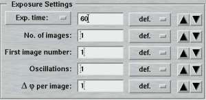
5. Exposure Settings
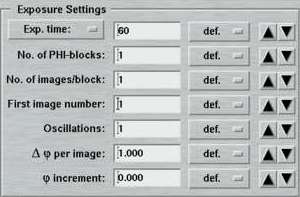
| Standard features | Advanced features |
|---|---|
|
|
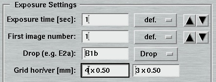
The entries of this area differ for "advanced" and "standard" layouts. Here is where you specify the parameters for controlling the exposures.
An exposure consists of the following sequence of actions:
- Open the shutter
- Drive Phi over a certain range (Delta-Phi)
- Close shutter
Note: When collecting data with the DECTRIS detectors - both the EIGER and the PILATUS3 - the shutter typically stays permanently open and closes only after the last image of the series. The read-out times of the pixel detectors are short enough, so the systematic errors by repeated open/close shutter operations are presumably larger than the ones introduced by keeping the shutter open during read-out. This mode of data collection is called "shutterless" and is an additional option used within the mardtb program flavour. It should be regarded as default.
The time it takes to drive Phi can be either a fixed exposure time or can be controlled by the X-ray dose as read in chamber 2. For an X-ray source with constant flux (i.e. home generators), X-ray dose controlled exposures are not recommended since time control is supposedly more accurate. On synchrotrons, X-ray dose controlled exposures used to be the typical way of collecting data. Recently, with the advent of very high brilliance sources and very stable storage rings, usage of time controlled exposures on synchrotrons may also become more appropriate. This is particularly true for short exposure times (< 10 sec). The choice of X-ray dose controlled exposures is only useful if there is a significant variation of X-ray dose within one exposure, which is going to be unlikely for short exposure times and a rapid completion of data collection. Most other affects can be compensated by the data scaling procedure. In shutterless data collection mode, DOSE mode is not available at all.
One important feature of the desktop beamline is the sophisticated Phi-motor stepper driver with 4 gears. This stepper driver allows for extremely smooth Phi-movements for longer exposures (> 30 sec) and thus enhances data quality. Depending on the given exposure time the program determines a suitable gear to move the Phi-axis. A consequence of this procedure is that the given exposure times may differ slightly from the exposure times the dtb eventually uses (but it is guaranteed that the exposure times are identical for all images of one set). For X-ray dose controlled exposures there is only 1 gear regardless of the resulting exposure times.
The "Exposure time"-menu allows the choice of using an X-ray dose instead of the actual exposure time. The X-ray dose to be entered is a magnitude that is difficult to handle. Therefore, the program converts the times given in the menu on the right hand side of the textfield into the corresponding X-ray dose units. It is strongly suggested to use this approach to setup the desired X-ray dose. The exposure time is given in seconds. Fractions are possible. In "shutterless" mode, the exposure time still refers to a single image and not to the duration of the entire data collection.
In the "standard features" mode, the "No. of images" determines how many images will be collected within this set. In the "advanced features" mode, this entry is replaced by the "No. of PHI-blocks" and "No. of images/block". A "PHI-block" is a subset of images contiguous in PHI. If this entry is set to 1, then the "No. of images per block" is identical to the entry in the standard features mode. Multiple PHI-block are mulitple subsets of images that differ by a rotation of 180 degrees in Phi. This method is useful for optimizing anomalous differences (e.g. for MAD-data). For 2 PHI-blocks with 50 images each, the data collection program will create 2 subsets of images ("A" and "B") containing 50 images each. The string "_A" and "_B" will be appended to the image root name and each subset starts with the same image number as given in the "First image number" field. The difference between subset A and B is a 180 degree rotation in Phi, but within subsets A and B all images are contiguous in Phi.
Multiple "Oscillations" are defined as the following sequence of actions during one exposure:
- Open shutter
- Move Phi over the desired Delta-Phi range
- Close shutter
- Move Phi back to start of exposure and repeat steps 1 to 3
An additional "advanced feature" is usage of a "Phi increment". This is defined as a Phi movement inbetween 2 images. This can be either a positive or a negative value. To clarify the situation here are 2 examples:
- Delta-Phi = 1 degree, Phi-increment = 44 degrees
1. image ranges from 0 to 1 deg.
2. image ranges from 45 to 46 deg.
3. image ranges from 90 to 91 deg.
etc.
Useful for accurate data indexing! - Delta-Phi = 1 degree, Phi-increment = -0.1 degrees
1. image ranges from 0 to 1 deg.
2. image ranges from 0.9 to 1.9 deg.
3. image ranges from 1.8 to 2.8 deg.
etc.
Useful for data with Phi overlaps!
6. Goniometer Settings
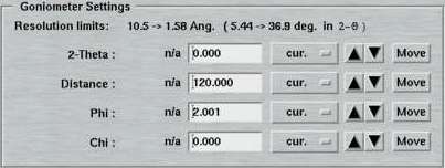
Here is where you specify the parameters for the detector-to-sample distance, starting Phi and 2-theta position during one data set. From here, you may move the motors directly by pushing the corresponding "Move"-button. In the standard layout, there is no option for driving the Chi motor (Phi-swing). In case this was necessary, you have to use the "Motors"-page.
Note, that the entries in the textfields do not necessarily coincide with the current motor positions and starting a data collection may therefore produce unexpected movements! It is therefore convenient, to use one of the options in the Edit menu for updating the motor positions for this set.
7. Collimator and Beam Settings
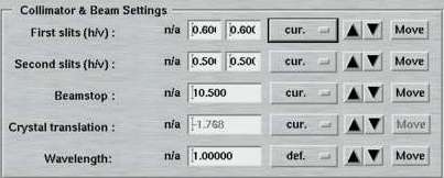
This entire area is available only in the "advanced features" layout. Here is where you specify the positions of the slits, beamstop and crystal translation to be used within one data set. In the "standard features" layout there will be no attempt to move any of those motors. If you want to make a crystal movement inbetween two data sets you would therefore have to use the "advanced features".
The "Beamstop" can be moved inbetween two data sets. A typical use of this feature would be a a data collection at high resolution with the beamstop relatively close to the crystal followed by a data collection of low resolution data. For low resolution data you would move the beamstop and detector further away from the crystal. It would also be helpful to reduce the slit size. In any case, you should confirm first that the beamstop is still going to cover the beam entirely when moving it further away. A primary beam on the image plate takes quite long time and very many scan/erase cycles to be wiped out!
The "Rel. crystal translation" entered here is relative to the current position. This is useful, since the absolute position for this motor is rather meaningless. The typical use is that a needle-shaped crystal is moved a fraction of a mm inbetween two data sets to compensate for radiation damage.
The "Wavelength" entered here is almost always used only for writing the correct value into the image headers. This is particularly important for synchrotron beam lines and it is very highly recommended to always fill in the appropiate values, since data processing programs may depend on image header values.
8. Options
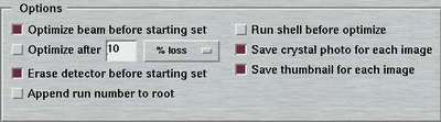
For every data set there are couple of options to be selected separately:
| Option | Description |
|---|---|
| Optimize beam before starting set | Optimize chamber 1 and 2 before starting with first exposure. Important, if DISTANCE or THETA has been moved! |
| Optimize beam after ... | Optimize chamber 1 and 2 during data collection Choice of optimizing after a given amount of images, after a given amount of elapsed time since the last optimization or after a given loss of X-ray intensity in chamber 2 (in percent). Please see note below. |
| Erase detector before starting set | Before starting with first exposure, the plate is erased. Useful if scanner has been idle for a while. |
| Append run number to root | In order to avoid creation of identical filenames when collecting multiple data sets, the no. of the data set is appended to the image root name as "_N" |
| Run before optimize | Runs a shell script (see below) before doing an optimization. The parameters passed are identical to those used with "Run before exposure" (see below). This feature can be used when doing a beamline optimization at a synchrotron using external motors (e.g. for the monochromator). |
| Save crystal photo for each image | If the PC features a frame grabber card, the program
either sends a command to program streamer or uses the
built-in video support
to record a photo of the crystal. The file format is "jpg" and
the file name is identical to the image file except the suffix.
Place of storage is the subdirectory photo of the
data directory. The subdirectory will be created automatically
if it doesn't exist. |
| Save thumbnail for each image | With this option, the output data images may be converted into a graphics image and shrinked to thumbnail size. This can be helpful to quickly scan through a data set to check for problems during diffraction. The way this option works is by calling a shell script called mar2thumb which may be customized according to user preferences. Please refer to chapter Thumbnails of section Output for more details. |
| Save spiral image | Raw spiral images can sometimes be useful for analyzing hardware problems. Note, that raw spiral images need to be transformed and corrected to give a Cartesian image. This choice will be presented only when running the program with option --admin. |
NOTE:
It is usually NOT recommended to reoptimize during a data collection of
one set, since this may have some impact on data quality. The only reason to
do so is if the position of the beam is unstable. Please note, that if
the X-ray source itself is unstable (i.e. if the beam goes away for some
time) a reoptimization carried out at a time when the beam is not present
will be counter-productive and severely affect the remaining data
collection!
9. Using Shell Commands
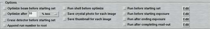
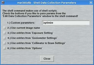
The "advanced features" in addition to the options described in the previous chapter offer the possibility to run a shell command at certain times during data collection. The following choices are available. The corresponding boxes must be checked to activate the option.
By pressing the "Edit"-button the "Edit - Shell"-window pops up. The way the shell commands work is quite simple. The program mar345dtb executes the shell script file $MARLOGDIR/dtb.csh and passes parameters from the editing process to that shell script. There are choices for passing the parameters from the parameter input areas to the shell script. The field for "Custom parameters" leaves room for any additional parameters you can think of. This method should allow you to execute any function you like by implementing a call to a program or whatever into dtb.csh. The program will continue with the next step of data collection after dtb.csh has exited. A template for file dtb.csh is given in the chapter dtb.csh of section Input.
10. Sample Changer Settings
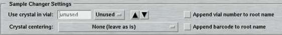
Here is where you specify the parameters to be used together with a sample changing device. These parameters can only be set when working with the "advanced features" layout. The choices are:
| Option | Description |
|---|---|
| Use crystal in vial ... | Select a carousel position for the crystal to collect data with - or choose "unused" |
| Crystal centering | Choose a method for centering the crystal:
|
| Append vial no. to root name | The vial no. of the crystal is appended to the image root name as "_N" |
| Append barcode to root name | The barcode of the crystal is appended to the image root name as "_STRING". |
When choosing to use the barcode as file name component, one can run into the
situation that the barcode is not readable in the mounting stage.
This is because during mounting there might be some residual liquid nitrogen on
the cap or ice crystals that make reading impossible.
In consequence, data will be collected with an unknown barcode and images
names are not as expected. After data collection, chances
for the barcode reader to
successfully read the barcode when putting the sample back into the carousel
are actually good. If this happens during a data collection, the program will
automatically take care to rename the collected images. What happens is that
the program writes out and executes a little shell script:
$MARLOGDIR/csc/setX.vialY.csh
where X is the set number and Y is the vial number.
This shell script can also be executed manually with the desired barcode as
the first command line argument, i.e.:
$MARLOGDIR/csc/setX.vialY.csh BARCODE
11. Crystal Plate Scanner Settings
When collecting data with the crystal plate scanner mounted in place, moving the PHI axis is no longer possible. A data collection therefore typically consists of single exposures without further possibilities of movement. It is possible to start the data collection at the current position or to let the instrument drive to a given drop whose coordinates in x,y (i.e. positions for motors XPS_X and XPS_Y) have been established previously. Therefore, the "Exposure Settings" section of the "Edit"-page provides only input fields for exposure time, number of images to be collected and for the drop to measure which may be left empty, meaning that the XPS_X and XPS_Y will stay where they are.