1. Introduction
- 1.1 The mar345 Image Plate Detector
- 1.2 The Standard mar Goniostat
- 1.3 General Remarks About Program mar345
- 1.4 Computer Requirements
1.1 The mar345TM Image Plate Detector
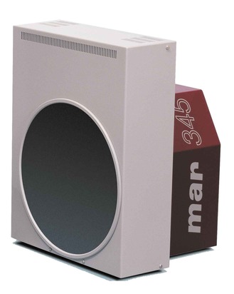
 The mar345 Image Plate Detector is a high speed scanner for so-called
image plates. Image plates possess a photo-stimulable phosphor, typically
BaF(Br,I):Eu2+. This compound is capable of storing X-rays in a broad energy
range (5 keV to 100 keV) by pumping electrons from the valence into the
conduction band where they can stay over longer periods of time (hours to days).
When stimulated by red laser light, typically around
630 nm wavelength, the trapped electrons return to the ground state while
emitting a blue photon (390 nm). The blue photons are counted by a
photomultiplier. Their quantity is proportional to the amount of absorbed X-ray
photons.
Image plate scanners are extremely sensitive integrating X-ray detectors. In contrast to electronical detectors like CCD's the read-out process is virtually noise-less. This is why even very low levels of X-rays can be recorded on image plates. Thus, image plate scanners are ideal detectors for all X-ray applications where noise becomes a crucial factor and where the detector read-out time is not the time-limiting step of the experiment.
Among all available image plate scanners, the mar345 Image Plate Detector outstands for its very short read-out time (down to 34 secs for a scan of 180 mm diameter) and its unsurpassed data quality. The key design feature is a single image plate of 345 mm diameter that is read out by driving a reading head over a spinning plate yielding spiral raw data. Since the plate itself is mounted in a fixed position the distance between the photon collector and the image plate surface is much smaller than in other image plate scanners making the mar345 the most sensitive detector of them all.
The mar345 Image Plate Detector can be used :
- stand-alone: to be integrated into an existing experimental setup
- with the standard mar goniostat
- with the mardtb "desktop beamline" goniostat
For use as a stand-alone detector or together with the standard mar goniostat, we offer an X-window based GUI - program "mar345" - and a terminal driven program called "scan345". Both programs run on Linux, Mac OS X and Windows (GUI in cygwin environment). In the next chapters the program "mar345" will be described in detail.
For use with the mardtb "desktop beamline" please refer to the mar345dtb User's Guide . The mar345 controller is a minicomputer that works as interface between the host computer and the detector (and goniostat). It features an Ethernet interface to the host-computer and translates commands from the outside world into appropriate hardware signals and viceversa. The controller is driven by a real-time operating system and implements the usual TCP/IP-services, i.e. ping, telnet, and ftp. Programs mar345 and scan345 communicate with the controller using standard Unix sockets on dedicated ports (4441 to 4444).
1.2 The Standard mar Goniostat
Before introducing the mardtb "desktop beamline" goniostat in 2001, most mar345 image plate detector systems have been shipped together with the standard mar goniostat. This instrument features the following components:
| Component | Features |
|---|---|
| Goniometer | - High precision PHI-axis - Motorized crystal rotation (PHI) - Manual crystal translation along spindle (z-axis) |
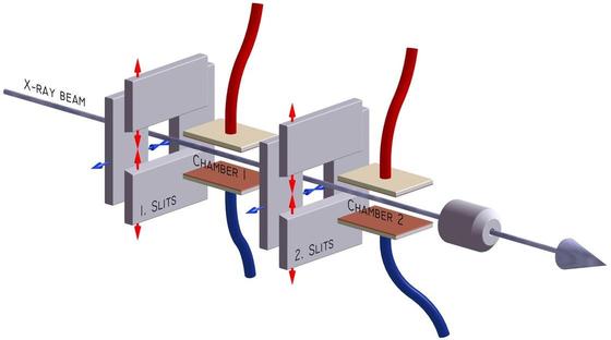
| Collimator | - 2 pairs of hor. and ver. slits followed by ionization chambers - Local beam shutter - CCD-microscope with viewing direction along X-ray beam - Movable beamstop |
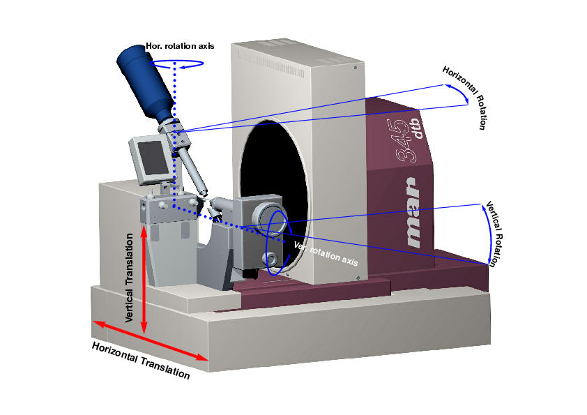
| Cardanic cradle | - Positional alignment motors: hor. and ver. translations of entire instrument - Directional alignment motors: hor. and ver. rotations of detector mount coupled to collimator |
| Detector mount | - Crystal-to-detector translation stage |
| Others | - Remote control unit for alignment motors |
All goniostat functions are controlled by the electronics built into the mar345 Image Plate Detector. Therefore, the programs that control the detector also control the goniostat. The scanner is connected to the goniostat via a high voltage cable (marked HV) and a 25-pin cable marked "X3" to transmit the signals to the stepper motors, the local beam shutter and the ionization chamber readings.

The geometrical setup of the mar goniostat is such that a beam passing through the collimator will hit a sample mounted on the goniostat. The cross-hair of a CCD-microscope is centered at the intersection of the primary beam with the sample mounted on the PHI-axis. On the detector translation stage a detector is mounted such that the center of the mar345 detector corresponds to the center of diffraction of the sample.
During the "alignment" procedure the goniostat motors drive into a position where the primary X-ray beam passes through the collimation system. To achieve this, 2 motors are required that translate the entire instrument along the beam and 2 motors that rotate the collimator and a frame with the goniostat and detector translation around the beam. The horizontal and vertical axes of rotation are centered at some point close to the first ionization chamber.
In order to understand how the alignment works it helps to have a look at the design of the collimator. It consists of 2 pairs of continuously variable slits followed by an ionization chamber each. The ionization chambers detect the intensity of the primary X-ray beam coming through the slits. The readings of the ionization chamber within the collimator are obtained by constantly monitoring currents as produced by the X-ray beam.
The alignment procedure usually consists of the following steps:
- Find beam in the first ionization chamber:
The horizontal and vertical translation motors must be moved until the primary X-ray beam passes through the first pair of slits. For this purpose it is helpful to widely open up both slits. - Find beam in the second ionization chamber:
Once the beam passes through the first chamber, the horizontal and vertical rotation motors must be moved until the primary X-ray beam also passes through the second pair of slits. For this procedure, the first pair of slits can be closed down to < 1.0 mm, but the second pairs of slits again must be opened up. Usually, when aligning the goniostat from scratch the beam does not go through the second pair of slits right away. Due to an inclination or tilt it is more likely that it hits the second pair of slits and gets swallowed before reaching the second ionization chamber. By driving the rotation motors the intensity readings in the first ionization chambers don't vary too much, since - in first approximation - the rotations are not coupled to the translations. In practice, you will observe some variations, though. - Optimize beam in the first ionization chamber:
At this stage, you should have some positive readings in both chambers, and it is assumed that only some fine tuning is required. Due to the weight of the detectors the statics of the entire instrument varies when driving the detector translation stage ("distance"). Due to the sensitivity of the ionization chambers you will observe a decrease of the readings of up to 20%. In other words: reoptimizing the beam in both chambers is strongly recommended when moving those motors.
For the optimization the first pair of slits are closed down to the approximate beam size, usually around 0.6 mm for Osmic mirrors. The horizontal and vertical translation motors for the first ion. chamber should then be moved until reaching their corresponding maximum. - Optimize beam in the second ionization chamber:
Both pair of slits are closed down, typically to 0.3 mm aperture. Again, the horizontal and vertical rotation motors should be moved around until reaching a maximum reading.
The standard mar goniostat comes with an additional remote control unit that is attached to the goniostat via a 15-pin and a 9-pin cable, respectively. The purpose of the remote control unit is to carry out an alignment of the instrument without having to be close to the instrument. A radiation enclosure normally prevents users from opening the X-ray shutter with any door of the enclosure open. But for alignment purposes, you need to have open beam. So the remote control unit typically should rest outside the radiation enclosure in order to carry out a safe optimization of the instrument.
The remote control unit contains push buttons to move the horizontal and vertical translation and rotation motors of the cardanic alignment system. It also features an LED-display for the ionization chamber, a gain selector button and a speed selector button. Please note, that for the remote control unit to work, the speed selector on the main instrument MUST be set to the ZERO position.
1.3 General Remarks About Program mar345
mar345 is an integrated graphical user interface for collecting data with the mar345 detector, either stand-alone or mounted on the standard mar goniostat. The program is fully menu driven and features options for setting up one or more data collection runs. It allows for fully automatic alignment of the instrument with the beam. It also features an area for image display and analysis.
The program is provided as binary executable for Linux, Mac OSX and Windows (cygwin).
Table 2: Supported architectures and operating system versions
| Architecture | Operating system |
|---|---|
| Linux 64-bit PC | CentOS/RedHat ≥ 6.0, Ubuntu ≥ 14.0 |
| Mac OS X | ≥ 10.11 Capitan (x86_64) |
| Windows 10 | Requires WSL (Windows subsystem for Linux), current Ubuntu or Debian. |
1.4 Computer Requirements
Program mar345 needs about 100 MB physical RAM, mainly for transforming incoming images from the detector. Most of the time, however, the program is not very busy and does not consume too much CPU time. For image display and other visualization purposes, a 24-bit color display is mandatory. The program requires a minimum screen resolution of 1280x1024 pixels. The program makes use of large transformation tables, so the minimum program installation requires a disk space of about 300 MB. Further components in the current mar-software distributions like the automar-data processing package may increase the required disk space to 400 MB.
The following specifications are considered as minimum requirements:
Table 3: Computer specifications
| Component | Requirement |
|---|---|
| CPU | Intel or AMD > 1 GHz |
| Memory (RAM) | >= 256 MB |
| Hard disk | >= 8 GB |
| Video card | 24 bit colors at ≥ 1280x1024 pixels @ > 70 Hz |
| Network card | Dedicated ≥ 10 MBit/s with IP-address 192.0.2.2 |
| Peripherals (optional) | DVD or CD-writer |
| Monitor | 19'' or larger, 1280x1024 pixels @ > 70 Hz |
| Required OS components | X-windows, X11-environment, openmotif libraries |
Important notes:
- All computer systems MUST be equipped with an additional Ethernet card.
- At installation time computers are expected to be FULLY FUNCTIONAL.


